|
Aerotrek |
|
Technical data
Airplane parameters
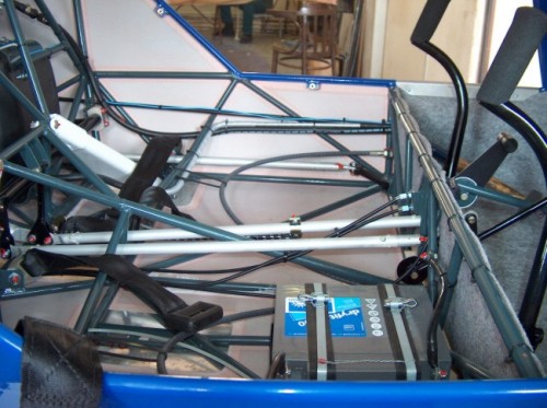
Electric system
Electric system is formed single-wire system of cabling with ground connection negative pole. Network supplies alternator with rectifier with 250W power and accumulator 12V / 16Ah. Board network is switched by a switch key of switch box. Individual circuits of appliances are switched by separate switches and protected by a safety limit switch.
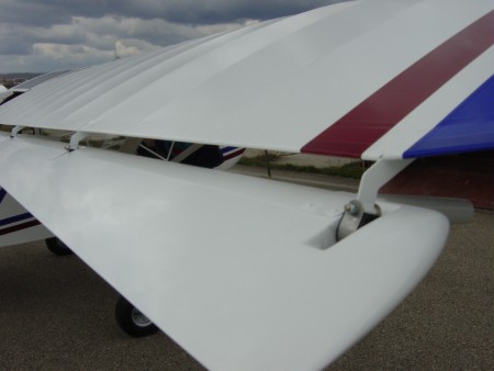
Tail unit
Classical tail unit is welded of the steel tubes. The fabric covered rudder is attached at three points. The control lever on its bottom part is used also for the tail wheel steering. The stabilizer is braced by two struts atteched to the bottom fuselage part. The elevator with non-divided leading tube is attached at 6 points with the control lever in its half. Elevator is equipped by a trim tab. Surface of horizontal tail unit is covered by fabric POLY FIBER.
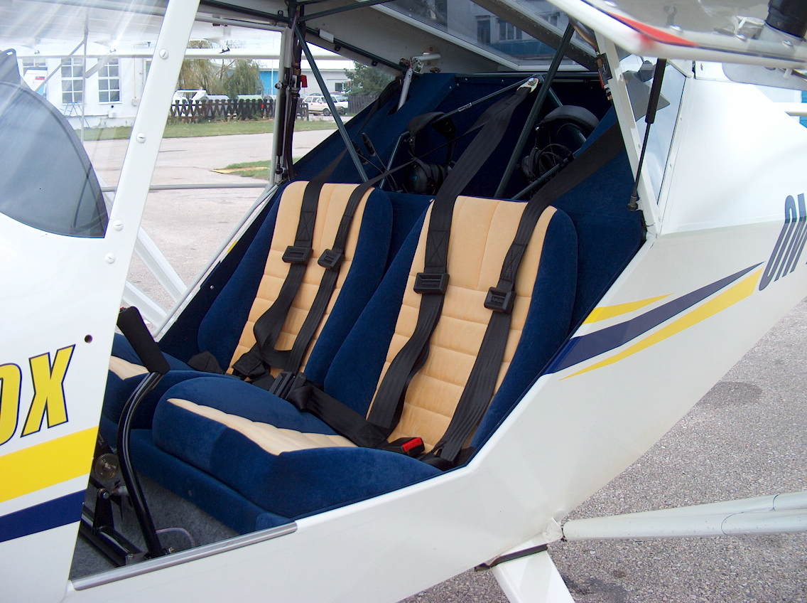
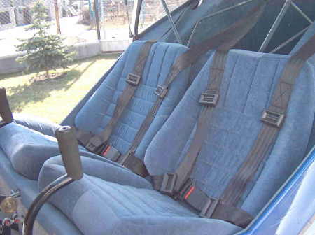
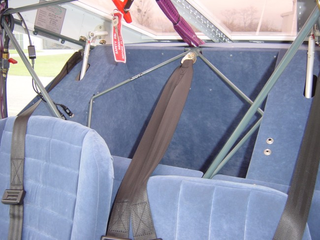
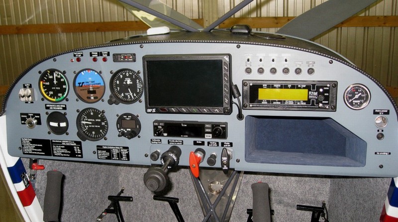
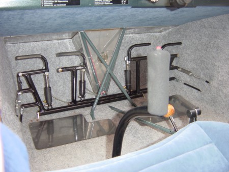
Cockpit and luggage compartment
The aircraft has two upholstered side-by-side. Each is equipped with four-point seatbelt.
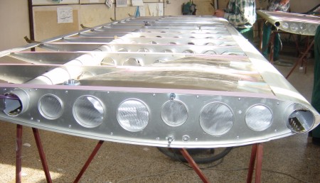
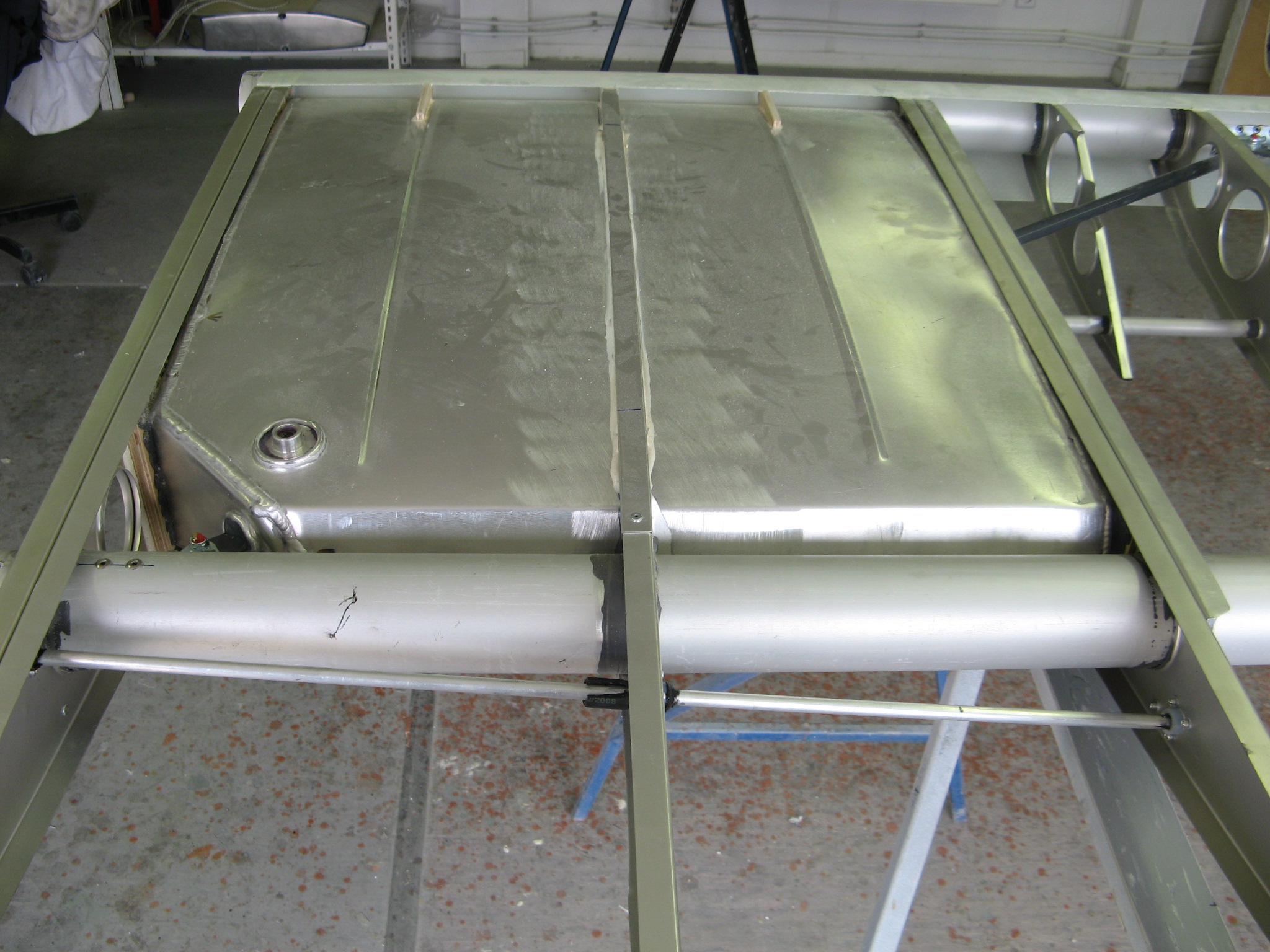
Luggage compartment with dimension 500 x 300 x 400 mm is situated behind the seats. Is designed for maximum 10 kg. Wing
Wing of rectangular platform with its own aerofoil section is of frame structure with two spar tubes and the system of diagonal struts and system of ribs. Al-alloy tubes of 63 mm diemater are reinforced in the hinges regions by tubes of corresponding diameter. A system of ribs consists of 14 ribs and of 13 aux. ribs supporting the fabric skin in the front wing area. In the horizontal plane the wing is braced by a system of diagonal steel spar tube. The 2x25,5 l fuel tanks are housed in the wing root part. Tanks are welded from Al-alloy sheet. The leading edge shape is guaranteed by a fiberglass part bonded in front of the spar tube. The trailing edge is fitted with an Al-alloy shaped batten. The wing is covered by synthetic fabric POLY FIBER, with applied stretching lacquer and sprayed by a first-rate exterior enamel. flaperons (Junkers flap) are attached through five hinges to the ribs under the wing trailing edge. The flapperon structure consists of Al-alloy tube and laminate sandwich (foam, epoxy resin, glass) formed in a negative mould. Both wings are attached to the fuselage in the upper part through the main tube hinges and in the bottoom part by the hinges of the "V" -shaped wing struts. The system of common rear wing hinge and tilt truss axes allows the wing to tilt along the fuselage rear part. This saves a lot of storage place and allows the road transport.
Fuel system
Fuel system has a total capacity of 56 l. It consists of two wing tanks (40 l each) and of an 5 l equalizing tank in the fuselage, connected through the pipes with the fuel cock and filter. Fuel level indicators are part of each tank, the minimim fuel warning light is mounted as standard.
Pitot - static system
Complete air pressure is sampled from a source placed on the right wing. Taking of static pressure to the instruments is from the inside room of the cockpit.
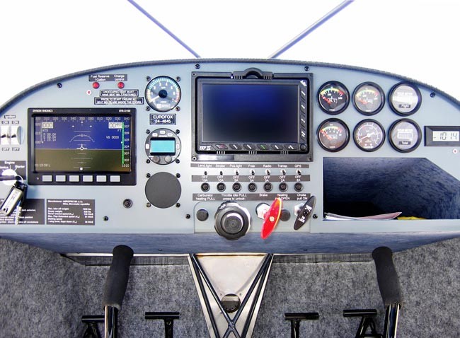
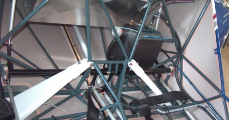
Control of the aeroplane
The aeroplane is equipped by dual stick control. Elevator and ailerons are controlled by a system of rods whereas the rudder is cable controlled. The wing flaps are controlled by the lever and rod and through the countershaft is threaded into aileron-flapperon circuit. Trim control is mounted as a standard. All engine controls are placed on the instrument board.
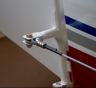
Rudder control - pedals of foot control are situated on the floor in front part of cockpit . Moving of pedals is transmitted on the rudder through steel cable.
Wing flaps - handle of wing flaps is situated in middle part of cockpit.
|
| Aeropro s.r.o. - designed by Michal Tonček |